


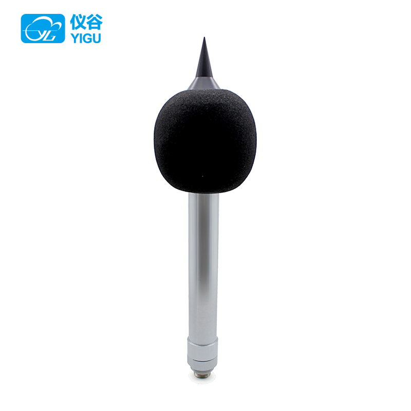
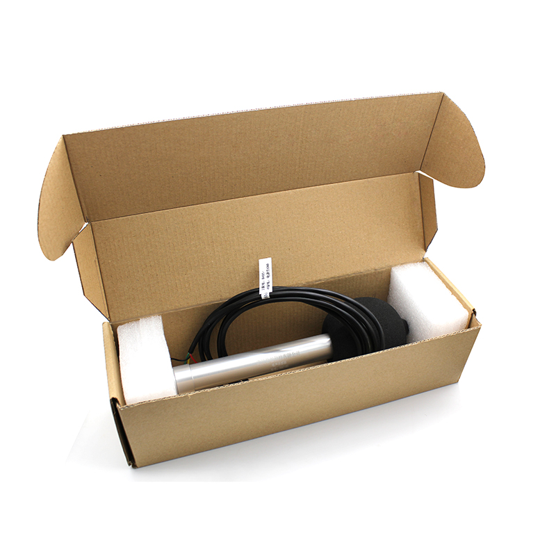
YGC-ZS Noise Sensor
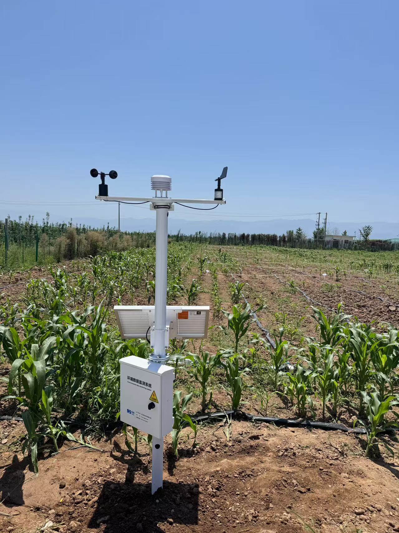
Application areas: It can be widely used for measuring industrial noise from various machines, vehicles, ships, electrical appliances, etc. It can also be used for measuring environmental noise, labor protection, and industrial hygiene.
WhatsApp: 8615271247832
Description
Product Introduction
The YGC-ZS Noise Sensor is a digital, modular, multifunctional sound level meter. It adopts a digital signal processing chip and digital detection technology, offering high reliability, good stability, wide dynamic range, and no need for range switching. It is widely applicable to industrial noise measurement of various machines, vehicles, ships, and appliances. It can also be used for environmental noise measurement, labor safety, and industrial hygiene assessments.
Product Selection and Technical Specifications
| GC-ZS Noise Sensor | ||||
| Basic parameters | Measurement Range | 30~130dB(A) | ||
| Sensitivity | -38±3dB(or12.6mv/Pa) | |||
| Resolution | 0.1dB | |||
| Accuracy |
±3dB, under ambient temperature 23±5℃, with frequency weighting compliant with IEC 61672 Type 2 standards, calibrated under an input signal of 94dB (1kHz). |
|||
| Power Supply | DC 5V | 9-30V | ||
| Output Signal | Current | 4~20mA | 0~20mA | |
| Voltage | 0~2.5V | 0~5V | 1~5V | |
| Serial Port | RS485(□Default Modbus □ASCII) | RS232(□Default Modbus □ASCII) | ||
| Cable Length | □ Standard 2.5 meters | □ Other: | ||
| Frequency Range | 20Hz to 12.5kHz | |||
| Response Time | 200ms, simulating the human ear's temporal response. | |||
| Calibrator | B&K (Bruel & Kjaer), multifunctional sound calibrator, model 4231 | |||
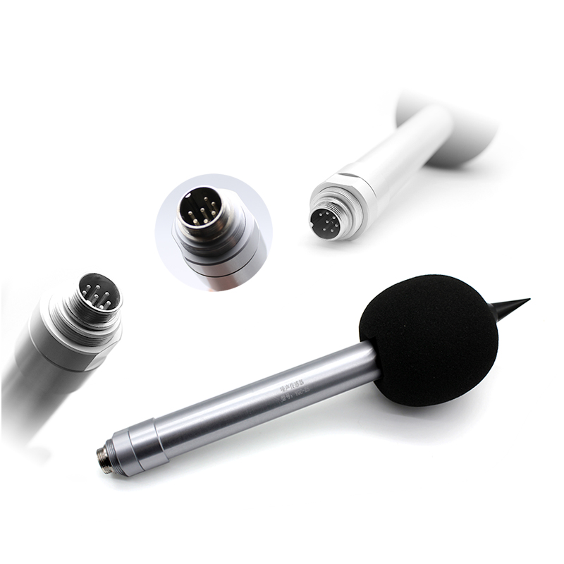
| Microphone | Electret microphone | |||
| Directivity | Omnidirectional | |||
| Microphone Size | 0.5 inches | |||
| Load Capacity |
With DC12V power supply, output impedance for current type ≤ 350Ω. With DC24V power supply, output impedance for current type ≤ 900Ω. Output impedance for voltage type ≥ 1KΩ |
|||
| Maximum Power Consumption | 500mW | |||
| Material | Aluminum alloy | |||
| Aluminum alloy | 165g | |||
| Gross Weight | 400g(including packaging and sensor cable) | |||
| Operating Environment | Temperature -40℃~80℃;Humidity ≤100%RHRH without condensation; | |||
| Protection Level | IP55 | |||
Wiring Method
(1)If the sensor is equipped with the company's instrument, directly connect the sensor cable to the corresponding interface on the instrument.
(2)If the sensor is purchased separately, the wiring sequence is as follows:
|
Wire Color |
Output Signal |
||
|
Voltage and Current |
RS485 |
RS232 |
|
|
Red |
Positive Power Supply |
Positive Power Supply |
Positive Power Supply |
|
Black |
Negative Power Supply |
A+/TX |
Connect to RX (Pin 2 of PC serial port) |
|
Yellow |
Signal |
B-/RX |
Connect to TX (Pin 3 of PC serial port) |
|
Green |
|
Negative Power Supply |
Negative Power Supply |
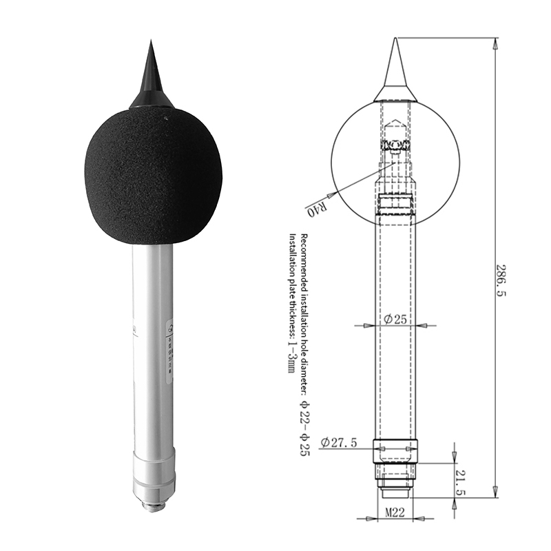
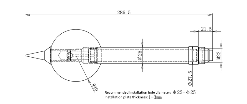
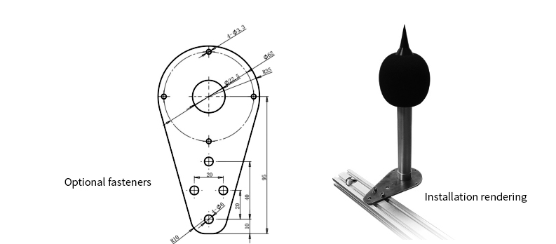
Sensor Dimensions
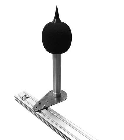
Installation Method
The metal rod at the bottom passes through the fixed plate (optional accessory) and is secured using a nut for installation.
Contact Us
Address:Room 01, 3rd Floor, Building 4, Gezhouba Sun City, No. 40 Gaoxin 4th Road, Donghu New Technology Development Zone, Wuhan,Hubei,China
Tel:+8619522958500
Whatsapp:+8615271247832
No Additional Information
Related products
Contact us
YIGU Sensors
Professional Weather Sensor & Weather Station Manufacturer
Telephone: +86-027-87915379
WhatsApp:+86 15271247832(Liang)
Email: info@whchenyun-tech.com
Address: Room 301, Building 4, Gezhouba Sun City Industrial Park, East Lake High-Tech Development Zone, Wuhan, Hubei Province, China
Get In Touch
Address
Room 301, Building 4, Gezhouba Sun City Industrial Park, East Lake High-Tech Development Zone, Wuhan, Hubei Province, China
Room 301, Building 4, Gezhouba Sun City Industrial Park, East Lake High-Tech Development Zone, Wuhan, Hubei Province, China
Phone
+86 19522958500
+86 19522958500
WhatsApp
+86 15271247832
+86 15271247832
SUBSCRIBE NEWSLETTER
- Get all the latest information on events, sales and offers. Sign up for newsletter:
Scan or click to chat

Scan to chat with us

Cloud Data
Scan to view cloud data
Copyrights © 2013-2026 Wuhan Chenyun Technology Co., Ltd. All rights reserved | Private Policy