


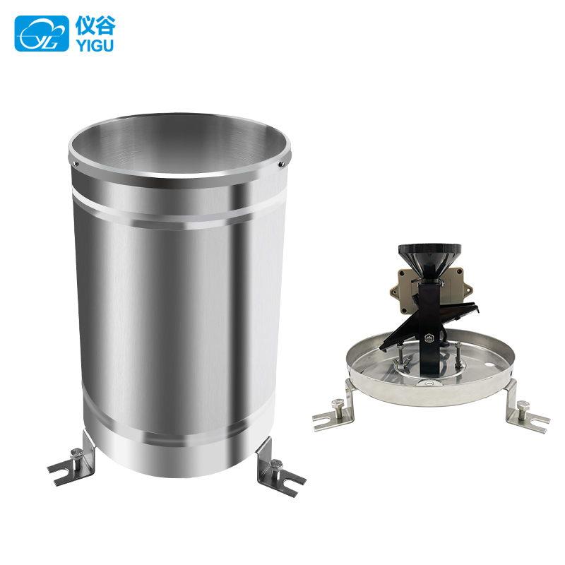
YGC-YL rainfall sensor
The YGC-YL rainfall sensor (transmitter) is used for remotely measuring liquid precipitation, precipitation intensity, and the start and end time of precipitation.
WhatsApp: 8615271247832
Description
Product Introduction
The YGC-YL rainfall sensor (transmitter) is suitable for use in meteorological observatories (stations), hydrological stations, agriculture and forestry, national defense, and other relevant departments for remote measurement of liquid precipitation, precipitation intensity, and the start and end time of precipitation. This instrument is produced, assembled, and calibrated in strict accordance with the requirements of the SL61-2003 hydrological automatic measurement and reporting system specifications, GB11831-89 national standards for remote sensing rain gauges in hydrological measurement and reporting devices, and GB11832-89 national standards for tipping bucket rain gauges.
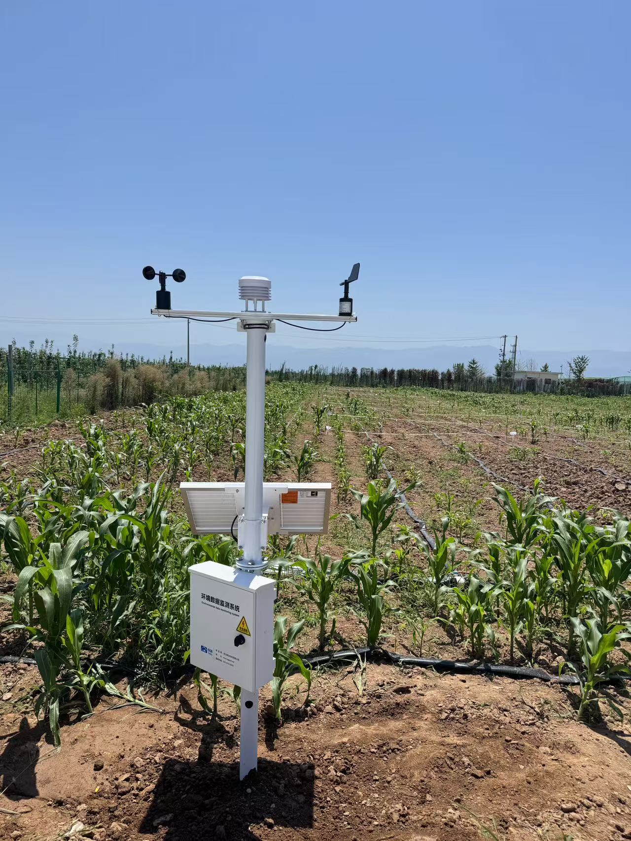
Application areas: It can be used in hydrological automatic monitoring and reporting systems, as well as automatic field monitoring and reporting stations, for the purposes of flood prevention, water supply dispatch, and power station reservoir water regimen management.
Technical Parameter
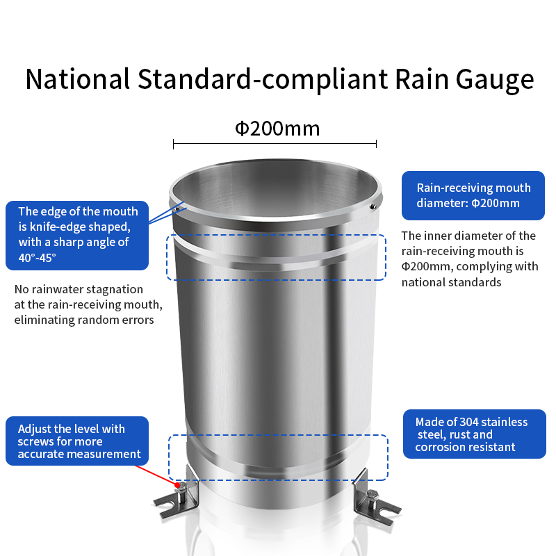
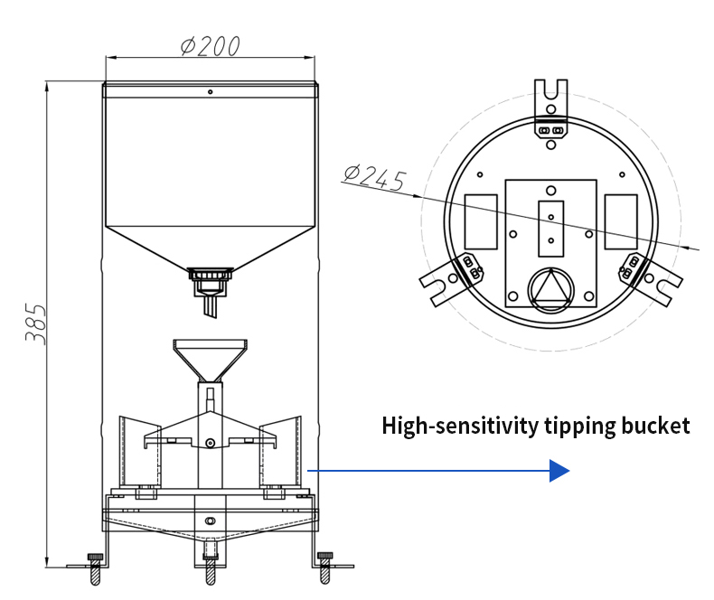
| Water-receiving diameter | Φ200 ± 0.6mm | |||
| Measurement range | ≤4mm/min (rainfall intensity) | |||
| Resolution | 0.2mm (6.28ml) | |||
| Accuracy | ±4% (indoor static test, rainfall intensity is 2mm/min) | |||
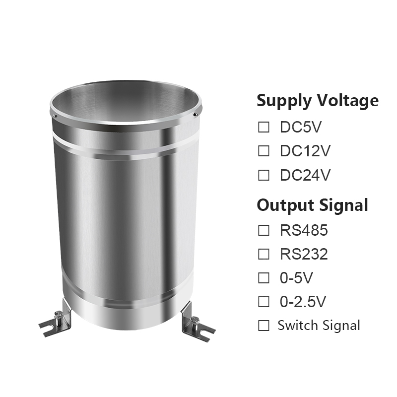
| Power supply mode | DC 5V (standard) | DC12V | DC24V | |
| Output signal | Switch signal | Switch signal: Reed pipe on/off (standard) | ||
| Voltage | 0~2.5V | 0~5V | ||
| Serial port | RS485 (default Modbus ASCII) | RS232 (default Modbus ASCII) | ||
| Sensor cable length | Standard: 5 meters | Other: | ||
| Operating temperature | 0~50°C | |||
| Storage temperature | -10°C~50°C | |||
| Product weight | Water-receiving bucket: 1700g, total weight: 3300g | |||
Wiring Method
1. If equipped with our company's weather station, simply connect the sensor to the corresponding interface on the weather station using the sensor cable.
Second, if the sensor is purchased separately, as the sensor outputs a set of switch signals, the cable connectors do not have a positive or negative side. Connect the sensor to the circuit as shown in the diagram.
III. If the sensor outputs other signals, the line sequence and corresponding functions of conventional sensors are as follows:
| Wire Color | Output Signal | ||
|---|---|---|---|
| Voltage type | Pulse | Communication type | |
| Red | Positive power supply | 2 wires, switch signal, no positive or negative distinction | Positive power supply |
| Black (Green) | Power ground | Power ground | |
| Yellow | Voltage signal | A+/TX | |
| Blue | B-/RX | ||
Product Size
Installation Instructions
■ The installation location of the sensor can be selected according to actual requirements, such as the ground, self-made large cylinders, iron column flange plates, or the roof of a building;
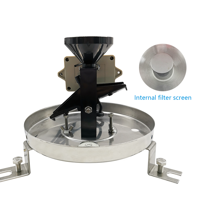
■ Remove the three Phillips screws under the barrel, take off the outer barrel, and remove the rubber band or tie under the funnel;
Adjust the three leveling screws on the chassis so that the bubble level indicates horizontal (the bubble stays in the center of the circle), and then slowly tighten the three M8 ×80 expansion screws for fixation; if the bubble level changes, readjustment is necessary;
■ Gently and slowly pour clear water into the sensor funnel, and observe the tilting process of the tipping bucket. Check whether data is being received on the collection instrument. Finally, pour in a fixed amount of water (60-70mm). If the data displayed on the collection instrument matches the amount of water poured in, it indicates that the instrument is functioning properly. Otherwise, it requires maintenance and adjustment;
■ Reinstall the outer barrel and secure it with 3 screws.
Explanation of sensor communication protocol
■ 1. If you are using a single sensor connected to a computer to directly read data, it is recommended to use the company's proprietary protocol (see page 4), which allows for intuitive display of data in ASCII code (hex sent, non-hex received);
■ II. If you are connecting multiple sensors to a PLC, configuring, or connecting to a programmable acquisition device, it is recommended to use the standard ModBus-RTU protocol (see page 2 for hex transmission and reception).
■ 3. If there are no special requirements, the device address in the sensor parameters defaults to 1, with a baud rate of 9600 and a protocol of ModBus-RTU.
注意事项
■ Please check whether the packaging is intact and verify whether the product model is consistent with the selected model; do not connect the wires while the power is on, and only power on after the wiring is checked and confirmed correct;
■ The length of the sensor cable can affect the product's output signal. When using, do not arbitrarily modify the components or wires that have been soldered in place at the factory. If modifications are necessary, please contact the manufacturer;
■ The sensor should be inspected regularly to remove dust, mud, leaves, and insects to prevent blockage of the water flow channel of the upper cylinder (funnel). The cylindrical filter screen can be removed and rinsed with clean water;
■ If there are dirt on the inner wall of the tipping bucket, it can be washed with water, alcohol, or aqueous detergent solution. It is strictly prohibited to wipe it with fingers or other objects, so as to avoid getting oil stains or scratching the inner wall of the tipping bucket;
■ During the winter freeze-up period, the instrument should be taken out of service and brought indoors;
■ Please keep the warranty card well and return it along with the product during maintenance.
Contact Us
Address:Room 01, 3rd Floor, Building 4, Gezhouba Sun City, No. 40 Gaoxin 4th Road, Donghu New Technology Development Zone, Wuhan,Hubei,China
Tel:+8619522958500
Whatsapp:+8615271247832
No Additional Information
Related products
Contact us
YIGU Sensors
Professional Weather Sensor & Weather Station Manufacturer
Telephone: +86-027-87915379
WhatsApp:+86 15271247832(Liang)
Email: info@whchenyun-tech.com
Address: Room 301, Building 4, Gezhouba Sun City Industrial Park, East Lake High-Tech Development Zone, Wuhan, Hubei Province, China
Get In Touch
Address
Room 301, Building 4, Gezhouba Sun City Industrial Park, East Lake High-Tech Development Zone, Wuhan, Hubei Province, China
Room 301, Building 4, Gezhouba Sun City Industrial Park, East Lake High-Tech Development Zone, Wuhan, Hubei Province, China
Phone
+86 19522958500
+86 19522958500
WhatsApp
+86 15271247832
+86 15271247832
SUBSCRIBE NEWSLETTER
- Get all the latest information on events, sales and offers. Sign up for newsletter:
Scan or click to chat

Scan to chat with us

Cloud Data
Scan to view cloud data
Copyrights © 2013-2026 Wuhan Chenyun Technology Co., Ltd. All rights reserved | Private Policy